$17.91
$22.75
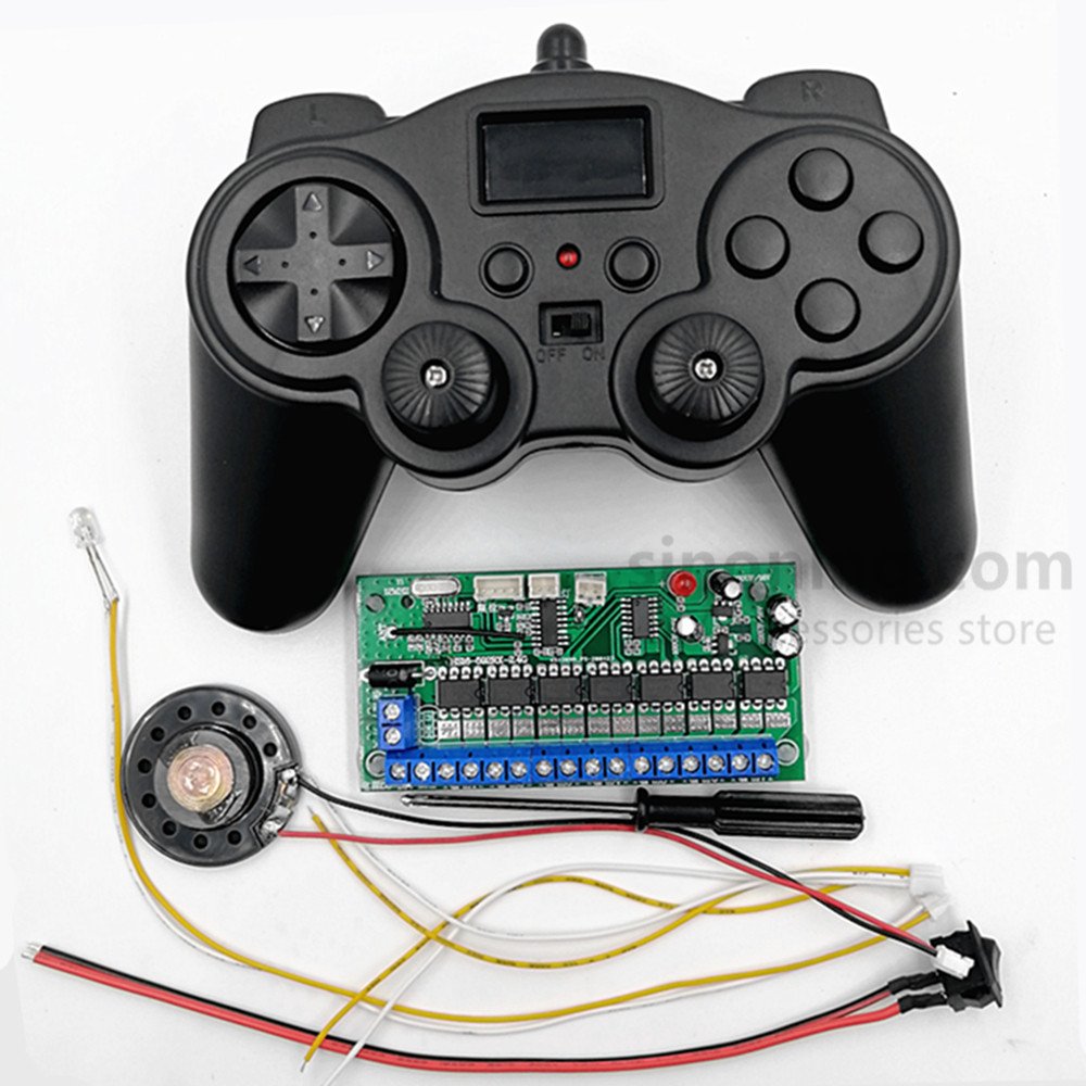
Description Product features: Mixed control of 2 motors with adjustable speed Control 2 servos or ESCs 2 single-channel self-locking controls [Application instructions] This 8-channel remote control receiving board uses 2.4G high frequency. It needs to be matched before use. Multiple sets will not be cross-frequency when used at the same time. The signal is stable and will not interfere with each other; 2-way self-locking flip mode remote control switch controls LED lighting and unidirectional motors; The left push rod can differentially mix the left and right travel drive motors to rotate forward and reverse, one forward and one reverse at the same time, and one reverse and one forward at the same time. It is suitable for remote control of model toy cars propelled by left and right drive motors (such as tanks, engineering vehicles, and remote control ships.), realizing forward, backward, left and right turns, and left and right turns on the spot. The right push rod can control 2 bidirectional servos or 2 bidirectional ESCs, or it can combine 1 bidirectional ESC and 1 bidirectional servo, which is suitable for remote control of high-speed remote control car models or ship models with 1 drive motor 1 steering servo. The bidirectional ESC controls the forward and reverse rotation of the drive motor to realize the forward and backward functions, and the bidirectional servo controls the left and right steering functions. 【Product parameters】 1. Remote control working voltage: DC2.8V~3.3V 2. Receiver board working voltage: DC 5V~7.4V, the actual maximum working voltage is 14V, and the maximum load current of the servo can only be within 1A. 3. Receiver board load power: The maximum load current of the left and right drive outputs is 5A, and the continuous load current is recommended not to exceed 4A. The maximum load current of the servo 1 and servo 2 outputs is 1A, and the maximum load current of the TT motor is 3A. 4. Transmitter board standby power consumption: 15ma 5. Receiver board standby power consumption: 25ma 6. Remote control frequency: 2.4GHZ 7. Remote control distance: about 100 meters on a spacious ground 8. Weight: remote control (excluding batteries) 128 grams, receiver board 23.5 grams. 【Binding method】 1. Press the TT button and LED button (binding button) in the middle of the remote control at the same time, hold down, then turn on the switch and power on. At this time, the red indicator light of the remote control flashes quickly, indicating that it has entered the binding mode. Turn on the receiving board switch and power on within 10 seconds. Note that the indicator light of the remote control flashes slowly several times and then goes out. At the same time, the red indicator light of the receiving board flashes slowly several times and then turns on, indicating that the binding is successful. 2. After the binding is successful, there is no need to bind again when using it again. If the receiving board is broken, a single receiving board can be re-binded and matched with the original remote control, and one transmitting board can be matched with multiple receiving boards. Tip: The remote control can remotely control multiple receiving boards to work at the same time. If this function is required, within 10 seconds after the remote control enters the binding mode, power on multiple receiving boards to match the remote control at the same time, so that one can remotely control multiple at the same time. [Operation Instructions for the Remote Control Receiver Board] 1. The left push rod can differentially control the forward and reverse rotation of the left and right travel drive motors, one forward and one reverse or one reverse and one forward at the same time. It is suitable for remote control of model toy cars propelled by left and right drive motors (such as tanks, engineering vehicles, and remote control ships.), realizing forward and backward, left and right turns, and left and right U-turns on the spot. 2. The right push rod can control 2 bidirectional servos or 2 bidirectional electric regulators, or it can combine 1 bidirectional electric regulator and 1 bidirectional servo, which is suitable for remote control of high-speed remote control car models or ship models with 1 drive motor 1 steering servo. The bidirectional electric regulator controls the forward and reverse rotation of the drive motor to realize the forward and backward functions, and the bidirectional servo controls the left and right steering functions. 3. The TT button controls the work of the TT motor on the receiving board, and the LED button controls the 5 cm white light LED lighting. Both the TT and LED buttons are in self-locking flip mode (press once to start, and press again to stop). [Wiring debugging instructions] Connect the drive motor wires to the left and right drive output pressure wire terminals of the receiving board according to the left and right distinctions, press the forward key, pay attention to the direction of the left and right motors, and it is normal if they move forward at the same time; if one motor moves forward and the other moves backward when moving forward, just swap the two wires connected to the backward motor and adjust the wiring; then press the left turn key, pay attention to the direction of the left motor moving backward, and the right motor moving forward, it is normal; if it is the opposite direction, swap the left and right drive motor connection wires on the receiving board. [Safety tips to prevent overvoltage and overload] 1. The standard operating voltage range of the receiving board: DC 5V~7.4V, the actual maximum operating voltage is 14V. When using a voltage higher than 7.4V, pay attention to the servo interface voltage output of about 5.5V, the load current is only 1A, and overload is strictly prohibited! If the load current of the servo used is too large, it will burn the BHO voltage regulator tube, and it may even cause the internal path of the BHO voltage regulator tube to burn through, causing the servo interface voltage to increase and burn the servo! ! ! 2. The maximum load current of a single circuit at the output end of the left drive and the right drive is 5A, and the continuous load current is recommended not to exceed 4A. The maximum load current of a single circuit at the output end of the servo 1 and the servo 2 is 1A, and the maximum load current of the TT motor end is 3A. 3. When selecting motors and servos, you cannot only look at the no-load or rated current. You must be aware of the detailed parameters of the maximum load current or stall current of the motor and the servo. The maximum load current or stall current must be within the load current value of the receiving board before it can be used; it is strictly forbidden to use overvoltage and overload, and do not use it blindly without knowing it. Improper use will cause damage to the receiving motherboard or burn the motor and servo ESC; 4. It is strictly forbidden to use high-power motors and high-speed motors! If the receiving board driver chip becomes hot after the connected motor or servo rotates, the motor cannot be driven to rotate, or the motor rotates very slowly, it cannot be used any longer, which may easily cause the board to burn 5. Special precautions: 1. The positive and negative poles of the remote control and the receiving board power supply cannot be connected in reverse, otherwise the board will burn! 2. All the electronic components of the receiving board are exposed, especially the pins of the components on the bottom. Safety protection measures such as insulation, waterproofing, and anti-corrosion should be taken during installation to avoid short circuit and burning caused by improper use! [After-sales terms and conditions] 1. Since the receiving board is a special product, the unstable operation of personal DIY (overvoltage, overload, wrong wiring, damage caused by failure to provide insulation protection during installation, etc.) will not be accepted for return and exchange once the receiving board is used; 2. Within 3 months from the date of purchase of the transmitting board and the receiving board, as long as the receiving board is not damaged by human factors such as driver IC damage, breakage, short circuit and burning, our store provides 1 free repair, and the return postage is borne by each party. [Frequently Asked Questions] 1. The remote control light does not light up after the battery is installed. Answer: 1. The positive and negative poles of the battery are installed in reverse, 2. The battery is dead or insufficient, 3. The battery compartment spring sheet or switch has poor contact. 2. The receiving board is connected to the power supply, but the indicator light is not on. Answer: 1. The battery is dead or insufficient. 2. The positive and negative poles of the battery are connected in reverse order with the positive and negative poles of the receiving board interface. 3. The line is short-circuited or broken. 3. The receiving board cannot drive one motor or multiple motors cannot be started at the same time. When the motor starts, the receiving board power indicator light flashes or turns off. Answer: 1. The receiving board battery is out of power or insufficient. 2. The battery discharge current is too small. 3. The battery output current cannot drive the receiving board to drive the motor. 4. The remote control and the receiving board cannot be paired. Answer: 1. The distance between the remote control and the receiving board is too far or too close during pairing, resulting in wireless signal loss or signal saturation. Normal pairing is best kept parallel at a distance of 50 cm; 2. The receiving board antenna is not erected. 3. The receiving board pairing crystal is interfered by metal objects. 4. The receiving board decoding IC is damaged. 5. Remote control signal delay, short distance Answer: 1. The antenna of the receiving board is not erected, 2. The installation space of the receiving board is too closed and there are metal objects, 3. Interference from the environment (signal tower, high-frequency signal and other working conditions), 4. No capacitors are installed at both ends of the DC motor, causing electromagnetic interference. 6. The indicator light of the remote control keeps flashing, and the receiving board often works in disorder Answer: The battery of the remote control is low and 2 new No. 5 batteries need to be replaced. Product version: v0.1 September 15, 2024 Related
Snrc Remote Control